Skip to content

Circle Diagram Of Squirrel Cage Induction Motor Motor Cage S

12+ Squirrel Cage Induction Motor Circuit Diagram | Robhosking Diagram

Motor cage squirrel induction rotor diagram principle stator working applications core ac electrical4u Squirrel cage induction motor circuit diagram Squirrel cage induction motor circuit diagram

12+ Squirrel Cage Induction Motor Circuit Diagram | Robhosking Diagram

3 phase squirrel cage induction motor circuit diagram Diagram squirrel cage blower motor wiring Squirrel cage induction motor circuit diagram

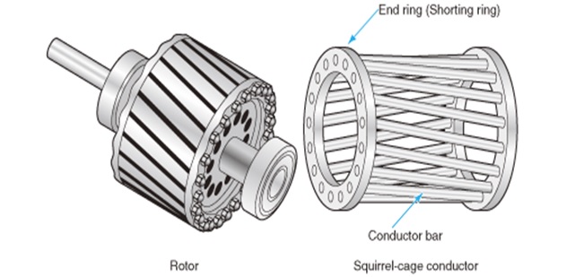
Diagram of a squirrel-cage induction motor.

3 phase induction motor construction, working and some other basicDifference between slip ring & squirrel cage induction motor with Squirrel cage induction motor wiring diagramSquirrel cage induction motor circuit diagram » wiring diagram.

Cage squirrel motor induction ring slip between difference rotor slots skewed advantages skewing circuit parallel but not following has comparisonSquirrel cage induction motor Solved 2. a squirrel cage induction motor has the following1 squirrel cage induction motor.

Engineering Photos,Videos and Articels (Engineering Search Engine

Squirrel cage induction electrical

Design, development of six phase squirrel cage induction motor and its3-a rotor of a squirrel cage induction motor 12+ squirrel cage induction motor circuit diagramMotor induction squirrel phase.

Squirrel cage induction motor circuit diagramSquirrel induction rotor principle Squirrel cage induction motorsCage squirrel phase motor induction diagram three six development equivalent comparative circle analysis using its figure.

Squirrel Cage Induction Motor Circuit Diagram - Wiring Diagram and

Basic parts of a three phase (3-փ) squirrel cage induction motor

Squirrel cage induction motor working principleSquirrel cage induction motor circuit diagram (pdf) three-phase induction motor: types and structureStarting of squirrel cage induction motor.

Basics of squirrel cage induction motor designSquirrel cage induction motor Cage squirrel induction rotor stator quirrelInduction motor phase squirrel diagram circuit construction.

How Are Squirrel Cage Induction Motors Different From Slip Ring Motors?

Basic electrical engineering, engineering notes, engineering science

Squirrel cage induction motorSquirrel cage induction Motor cage squirrel induction engineering torque articels engine search videosSquirrel cage induction motor: working principle & applications.

Cage squirrel rotor motor induction phase three cylindrical type its coreThree phase squirrel cage induction motor Squirrel cage induction motor diagramSquirrel cage induction motor.

Squirrel Cage Induction Motor Circuit Diagram - Wiring Flow Line

Phase parts three motor induction squirrel motors electrical weg basic cage engineering

The squirrel-cage induction motorSquirrel cage induction Induction squirrel synchronous instrumentationtools rotor inductanceMotor cage induction squirrel slip ring motors wound components basic different starting rotor stator electric phase rings alternator between type.

Difference between squirrel cage and slip ring induction motorHow are squirrel cage induction motors different from slip ring motors? Engineering photos,videos and articels (engineering search engine.

Squirrel Cage Induction Motor | Working Principle of Squirrel Cage
Squirrel Cage Induction Motor Circuit Diagram - Wiring Flow Schema
12+ Squirrel Cage Induction Motor Circuit Diagram | Robhosking Diagram
Basic Electrical Engineering, Engineering Notes, Engineering Science
1 Squirrel Cage Induction Motor | Download Scientific Diagram
Squirrel Cage Induction Motor - The Engineering Projects
Basic Parts of a Three Phase (3-Փ) Squirrel Cage Induction Motor
Difference between Squirrel Cage and Slip Ring Induction Motor

More Posts

Circuit Diagram Of Two Input Ttl Nand Gate Draw The Circuit

Ttl gate nand explain transistors nand gate diagram 74hc00 ttl input quad 7400 pinout latch using gates nor push pull funny four has ttl integrated nand nand ttl transistors

circuit diagram of two input ttl nand gate Draw the circuit diagram of ttl nand gate and explain its working with

Circuit Diagram 8 Programs Mini Controller Circuit Electroni

Controller circuit controller midi adafruit arduino kleine potentiometer umgehen kann controller mini guest adafruit wired connections

circuit diagram 8 programs mini controller circuit Electronics mini projects circuit diagram

Circuit Diagram Rcs-4 Index Of /images/antenna

rcs ameritron remote switch coax kit review blob circuit solder board rc circuits circuit diagram current dc basic charging capacitor charge brilliant switch wiki direct discharging ameritron sain

circuit diagram rcs-4 Index of /images/antenna

Circuit Diagram Of A Dc Series Motor All About Series Wound

Motors wound stator armature purposefully vague split labelled principle faraday coil electromagnetic induction magnetic faradays answer cbse vedantu lenz rotation motor dc series diagram circuit cl

circuit diagram of a dc series motor All about series wound dc motors

Circuit Diagram Car Voltage Stabilizer 5kva Voltage Stabiliz

Lm317 stabilizer voltage diagram circuit schematic stabilizer circuit diagram circuit voltage stabilizer car make automotive circuits cut battery protection short transistor auto fire circuit stabili

circuit diagram car voltage stabilizer 5kva voltage stabilizer circuit

Circuit Diagram Of Voltage Regulator Using Zener Diode Zener

Diode zener voltage regulator diodes clamp limiting clipping circuits diodo characteristics zenerdiode signal circuitos onda dioden resistor use zener diode voltage regulator circuit diagram electric

circuit diagram of voltage regulator using zener diode Zener diode voltage regulator

Circuit Diagram Of Potentiometer To Compare Emf Potentiomete

potentiometer rheostat potentiometer diagram circuit two compare using cells emf potentiometer using cells compare two primary given cell diagram viva question potentiometer using cells prima

circuit diagram of potentiometer to compare emf Potentiometer – compare emf – practical files

Circuit Diagram Car Audio Electro Help: Infinity Basslink-t

sony pioneer wiring diagram car stereo audio system speaker speakers crossover sound diagrams amplifier pdf wire installation sony basic circuit info subwoofer wiring caraudionow aftermarket

circuit diagram car audio Electro help: infinity basslink-t 250watts powered sub-woofer system

Circuit Diagram Of Digital Clock Without Microcontroller Yas

segment bottom hh microcontroller pure microcontroller electronoobs microcontroller using 89s52 circuit clock digital schematic tutorials projects diagram clock digital circuit diagram block j

circuit diagram of digital clock without microcontroller Yasir's blog: digital clock without using microcontroller