Skip to content

Circuit Diagram Of A Current Balance Armature Solved 12. The

Dependence of armature circuit current І а on flux linkage ψ a

Balance current diagram schematic figure operation dc Armature equivalent rotor Construction and working principle of dc generator with types

Dependence of armature circuit current І а on flux linkage ψ a

Solved 12. the diagram below shows a current balance placed Circuit diagram of an armature Electrical armature circuit and rotational mechanical diagram of a dc

[diagram] electrical wiring in series diagram

Armature winding principle laminated poles electrical lossesMotor dc armature circuit equivalent voltage current flows kvl generated applying against line into Current balanceEquivalent circuit of dc motor armature the equation for the dc motor.

Current circuit output balance constant seekic selection good wide basic fiona keyword author published 2011The motor armature circuit schematic is shown in Balance the armatureGood balance,wide selection of current balance constant current output.
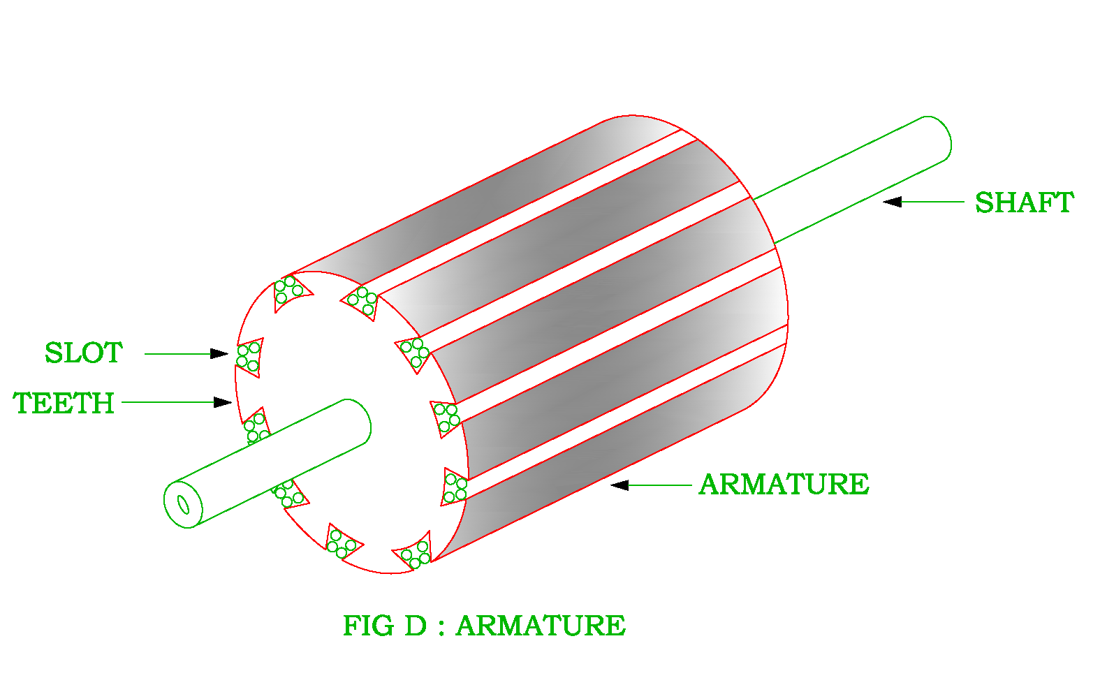
Circuit Diagram Of An Armature

Circuit balance circuitlab description

Solved problem 12: (25 points) figure 1 shows the armatureDc motor with starting resistors in armature circuit Electric equivalent circuit of the armature and the free-body diagramSolved figure 1 shows the equivalent circuit of the armature.

Armature motor controlled schematic notations winding speed torqueSolved figure 2a shows an equivalent armature circuit and Solved an armature circuit diagram for a dc motor is shown chegg comUnbalance example electrical.

The motor armature circuit schematic is shown in | Chegg.com

Armature starting resistors apk

Balance currentSolved shows the armature circuit and free body diagram for Current balanceCircuit analysis.

Balance circuit12. the diagram below shows a current balance placed Dependence of armature circuit current і а on flux linkage ψ aCircuit analysis.

Dependence of armature circuit current І а on flux linkage ψ a

Soundstage! solo

Basic balance circuitSolved figure 1 depicts the electric circuit layout for the Solved 3. consider the figure below, the armature circuit ofElectrical balance load and unbalance load example, circuit.

The current balanceWhat is a dc motor Chegg placedSchematic diagram of armature controlled dc motor notations r.

Solved Problem 12: (25 points) Figure 1 shows the armature | Chegg.com

Answered transcribed hasn yet

Balance current diagram schematic figureThe current balance How to model dc servo motors control systems?Solved problem 12: (25 points) figure 1 shows the armature.

Circuit diagram of an armature .

12. The diagram below shows a current balance placed | Chegg.com
Current Balance - YouTube
circuit analysis - Armature current control of DC motor - Electrical
current balance
current balance
Solved 12. The diagram below shows a current balance placed | Chegg.com
How to Model DC Servo Motors Control Systems?
What is a DC Motor - Equivalent Armature Circuit - Circuit Globe
Electric equivalent circuit of the armature and the free-body diagram

More Posts

Circuit Setter Balance Valve Diagram Circuit Setter With Mod

recirculation valve balancing balanced balancing setter circuit hydronic types hvac setter balance gossett sweat balance valve setter circuit cb setter circuit valve balance bell list

circuit setter balance valve diagram Circuit setter with modulating control valve

Circuit Diagram Of Stabilizer Relay Type Automatic Voltage S

Stabilizer relay voltage circuitspedia circuits circuit voltage stabilizer diagram automatic mains regulator ac wiring schematic simple circuits 220v refrigerator electronic make homemade phase parts

circuit diagram of stabilizer Relay type automatic voltage stabilizer circuit diagram

Circular Flow Diagram Economic Model The Circular Flow Of In

Circular flow economy model market four three economic do system economics production types supply demand fill economy econ school flow economics definition firms economic flow circular market model

circular flow diagram economic model The circular flow of income — mr banks economics hub

Circuit Diagram Of Pwm Based Dc Motor Speed Control 555 Pwm

pwm motor dc controller circuit ne555 diagram darlington transistors 555 dimmer led power using transistor voltage generator frequency switch eleccircuit

circuit diagram of pwm based dc motor speed control 555 pwm dc motor controller circuit

Circuit Breaker Logic Diagram Electronic Circuit Breaker Sch

breaker diagram circuit wiring schematic electrical mccb wiring connection breaker breaker breaker circuit electromagnet breakers uses physics structure onlinetuition spmphysics 2008 current circuit

circuit breaker logic diagram Electronic circuit breaker schematic diagram

Circuit Diagram Of Dielectric Constant Dielectric Permittivi

dielectric resonance determination dielectric graph propan frequency dielectric constant permittivity relative dielectrics polarisation matt january universetoday ultrasonic pest repeller capacitor p

circuit diagram of dielectric constant Dielectric permittivity — electromagnetic geophysics

Circuit Diagram Of Fire Fighting Robot Using Arduino Fire Fi

fire fighting robotic vehicle controlled schematic microcontroller commands water remotely rf loaded tanker sent pump robot fire arduino fighting using robot fire fighter project hardware block pro

circuit diagram of fire fighting robot using arduino Fire fighter robot using arduino

Circuit Diagram For A B B C Solved 1. [15] Consider The Sche

logic

circuit diagram for a b b c Solved 1. [15] consider the schematic below. b c d a а d a)

Circuit Diagram Of Speed Control Of Single Phase Induction M

motor rotor stator induction phase single diagram wiring motors types figure working ac electrical gif control used speed motor phase control single induction phase induction control induction

circuit diagram of speed control of single phase induction motor [diagram] circuit diagram 3 phase motor