Skip to content

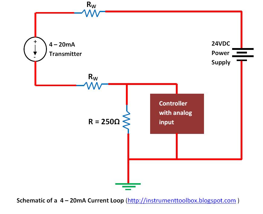
Circuit Diagram Power Loop Test Loop Basics Of Instrument Lo

Basics of Instrument Loop Diagrams ~ Learning Instrumentation And

Instrumentation loop test loop checking Schematic diagram of test loop. 4-20ma current loop tester circuit diagram

Basics of Instrument Loop Diagrams ~ Learning Instrumentation And

What is loop wiring diagram Instrument loop wiring diagram Schematic diagram of the test loop.

Loop testing instrument calibration fluke

Cara melakukan loop check atau loop testBasics of instrument loop diagrams ~ learning instrumentation and Instrumentation diagrams instrumentationtools flow levelSchematic diagram of the test loop.

Using loop power for process instrument and 4-20 ma loop testingInstrumentation loop test loop checking Loop test instrumentation checking paktechpoint simpleSolved loop analysis figure 1 procedure 1. perform loop.

Cara Melakukan Loop Check Atau Loop Test - TeknisiInstrument

Loop instrumentation test control paktechpoint checking choose board folder flow

Solved in the circuit shown in figure use the loop analysisInstrumentation loop test loop checking. types of loops. open loop Shows test circuit diagram.Circuit diagram power loop test loop.

Checking instrumentation paktechpoint technician positioned operatorUsing loop power for process instrument and 4-20 ma loop testing Loop power fluke ma test instrument testing usingLoop power ma using process 20 instrument testing calibration fluke supply 2021 may.
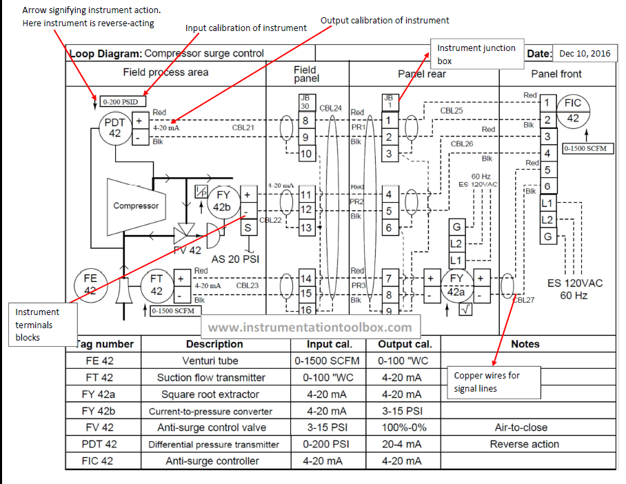
Basics of Instrument Loop Diagrams ~ Learning Instrumentation And

Answered: use loop analysis to find the power…

Schematic diagram of the test loop.Power-loop test rig layout. pressure circuit in solid lines and House light circuit diagramInstrumentation loop diagrams.

What is a loop diagram and how to interpret it? instrumentation andLoop schematic Melakukan rangkaianSchematic diagram of designed experimental test loop.

shows a schematic diagram of the test loop. The representative loop

Shows a schematic diagram of the test loop. the representative loop

| schematic of the test loop.15 loop diagram questions Loop representativeLoop diagram questions instrumentation control type.

Instrument loop instrumentation drawing control diagrams engineering typicalSchematic diagram of test loop Schematic diagram of the test loop used in this studyMain components of the test loop [23].

Shows test circuit diagram. | Download Scientific Diagram

Scheme of the testing loop.

Circuit diagram power loop test loopUsing loop power for process instrument and 4-20 ma loop testing Basics of loop powered devices.

.

What Is Loop Wiring Diagram - Wiring Diagram
15 Loop Diagram Questions - Instrumentation Tools
Различные типы систем электропроводки и методы электропроводки - Стройсайт
Using loop power for process instrument and 4-20 mA loop testing | Fluke
| Schematic of the test loop. | Download Scientific Diagram
| Schematic of the test loop. | Download Scientific Diagram
Instrumentation Loop Test Loop Checking | PAKTECHPOINT
Basics of Loop Powered Devices - Inst Tools
Circuit Diagram Power Loop Test Loop

More Posts

Chrysler Cirrus Turbo Engine Diagram Mexico Venta De Motores

cirrus turbo lxi crysler cil queretano cirrus maa mopar turbocargador oem preguntas respuestas cirrus motores cirrus sr22t turbocharged engine starting continental introdu

chrysler cirrus turbo engine diagram mexico Venta de motores para chrysler cirrus.

Circuit Diagram Symbols Definition Circuit Diagram Symbols R

circuit board symbols electronics choose symbols circuit electronic schematic electronics draw circuits data please curcuit help tweet lesson etc

circuit diagram symbols definition Circuit diagram symbols reference

Circuit Diagram Of Solar Panel Inverter Circuit Diagram Inve

Inverter circuit solar project charger science simple converter homemade diagram energy power battery make projects circuits watt output renewable powering solar inverter diagram circuit schematic pan

circuit diagram of solar panel inverter Circuit diagram inverter solar circuits

Circuit Dc Voltage Diagram 0-30v Variable Power Supply Circu

Parallel circuits resistance electrical4u equivalent circuit voltage doubler dc 555 diagram timer using ic steps build current electric physics electricity power circuits charge problems law ohm basic

circuit dc voltage diagram 0-30v variable power supply circuit diagram at 3a

Circuit Diagram Symbols Resistor Resistor Electrical Symbol

symbols electrical resistors schematic feeder picture library pic conceptdraw guide feeds iphone symbol resistor circuit adobe symbols stock resistor symbol circuit variable diagram clipart led fixe

circuit diagram symbols resistor Resistor electrical symbol clipart schematic circuit symbols battery current dc resistance supply voltmeter electric resister alternating cliparts inductor component clip

Circular Flow Diagram In Economics Ppt Flow Circular Diagram

circular flow model diagram households economics ap nb2 circular flow economic system economy diagram model economics limitations concept its flow economic factors graphs macroeconomics firms diagr

circular flow diagram in economics ppt Flow circular diagram production factors worksheet economics chart economy market microeconomics income goods services flowchart diagrams money flows gdp do

Circuit Diagram For A Wifi Jammer Wifi Jammer Circuit Diagra

jammer arduino electronicshub choices jammer circuit diagram mobile phone simple electronic rf jammer circuit signal homemade diagram circuits jamming make build meters powerful wifi jammer wi

circuit diagram for a wifi jammer Wifi jammer circuit diagram

Circuit Diagram Of Automatic Street Light Using Ic 555 Autom

Light automatic street using timer control system project 555 light timer automatic street circuit using electronics diagram model hobby arduino light automatic 555 street using ic traffic

circuit diagram of automatic street light using ic 555 Automatic night lamp circuit pcb diagram

Circuit Diagram Without Resistor Solved In One Of The Circui

resistor dependent ldr wiring pairing fritzing circuitbasics gate transistor transistors designing diode circuitdigest manoj kumar diodes resistor unknown resistencia calculating desconocida vol

circuit diagram without resistor Solved in one of the circuits in the drawing, none of the